Switch Setup For Multiple VLANs
About
This guide is about how to configure multiple VLANs for a router with a single network interface card (NIC) with the help of port tagging on an unmanaged switch. This is the second post in a series on networking with OPNsense, with the goal of supporting a small homelab. If you want to follow along with the series, start with OPNsense Router Intro.
Prerequisites
Required hardware:
- Netgear GS308E 8 port 1GB switch (or equivalent/better) with an ip address within your router’s ip address range as specified by router’s ip and subnet mask (i.e. ip of 192.168.0.1 and subnet mask of 255.255.255.0 gives a range from 192.168.0.2 to 192.168.0.254).
Instructions
Navigate to the switch’s ip address (located on the back of the device if you haven’t set a static ip for it) and enter the provided username and password. Change this on first login and save the credentials in a password manager along with the ip.
- Click on the ‘VLAN’ tab.
- Select 802.1Q in the sub menu underneath the VLAN tab.
- On the left hand side, select Basic and disable it if it’s enabled.
- On the left hand side, expand the Advanced dropdown by clicking the down arrow, then select VLAN Configuration.
- Under Advanced 802.1Q VLAN Status, select ‘Enable’ and apply.
- In the box labeled VLAN ID, type 100 and then click ‘Add’. Repeat with values 901 and 902. These are the separate VLANs we are creating.
- On the left hand side, select VLAN Membership.
- In the dropdown box labeled VLAN ID, select VLAN 100. Click the ports to mark them Untagged (U), Tagged (T), or leave empty (no indicator). The table below shows which ports should be tagged or untagged. Repeat with the other VLANs, making sure to hit apply after all ports have been correctly assigned.
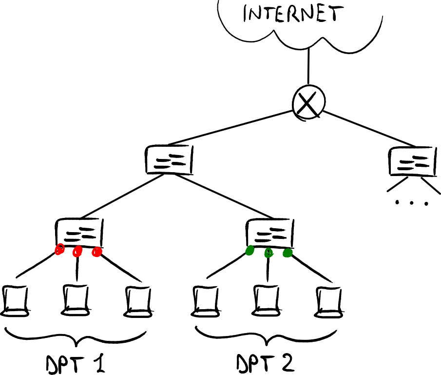
This home network has three VLANS:
| VLAN ID | WAN/LAN | PORTS |
|---|---|---|
| 100 | WAN | 1 2 |
| 901 | LAN | 2 3 4 8 |
| 902 | LAN | 2 5 6 7 |
In each VLAN, port 2 is marked ‘Tagged’ and the other ports listed above in the ports column are ‘Untagged’. Any unlisted ports should be left empty.
After each VLAN Membership has been configured and applied, we must configure the Port PVIDs:
- On the left hand side, select Port PVID.
- Set each port to its VLAN by selecting the checkbox for each port in the VLAN, entering the corresponding PVID value into the PVID entry box, and then selecting apply:
| Port | PVID |
|---|---|
| 1 | 100 |
| 2 | 901 |
| 3 | 901 |
| 4 | 901 |
| 5 | 902 |
| 6 | 902 |
| 7 | 902 |
| 8 | 901 |
| Cleanup | |
| Now that all the ports have been assigned to the correct VLANs, we need to remove them from the default assignment (VLAN 1). Go Back to VLAN Membership, select VLAN ID 1, and set each port to empty. Select Apply. |
System Management If you want to change the switch’s ip to a different network such as 10.0.0.x instead of 192.168.0.x, you should set a static ip from your router’s DHCP server. You may have to power cycle the switch for the router’s DHCP server to assign the new ip. If you can’t see the switch in the router’s DHCP leases of attached devices, you can use Netgear’s Switch Discovery Tool to search for the ip of the switch on your network. I downloaded that tool on my phone using my cell network, then transferred the files over to my PC via USB. I had to go into my phone’s USB settings to allow file transfers via USB.
If you still can’t discover the ip, make sure you are on the same network as the switch and everything is connected by ethernet cables. If you are connected to the internet and the switch doesn’t appear, you are probably on a different network. The switch may have defaulted to the default network (192.168.0.1) while you are on a different one (10.0.0.1). For this example let’s assume your network is 10.0.0.1 and the switch is on the default network 192.168.0.1. Your network ip addresses may be different, so adjust the example accordingly. On Windows, you can manually set your pc to the other network by going to Settings > Network & Internet > Ethernet:
- Select ‘Edit’ next to IP assignment: Automatic (DHCP)
- Select the drop down menu and select ‘Manual’.
- Toggle the IPv4 slider to the ‘On’ position.
- For the IP address, enter 192.168.0.200
- For the Subnet mask, enter 255.255.255.0
- For the Gateway, enter 192.168.0.1
- For the Preferred DNS, enter 8.8.8.8
- Select ‘Save’
- Close and reopen Netgear’s Switch Discovery Tool. Select the network 192.168.0.200 and then select ‘Start Searching’. Your switch should be displayed along with its ip. You should be able to navigate to this ip in your browser to continue setup.
Some users have reported issues with the switch not accepting the ip assigned by the DHCP server. In this case you can set the ip manually by going to System > Management > Switch Information:
- Make sure ‘Refresh’ checkbox is unchecked
- Change DHCP Mode to Disable
- Set IP address to the same static ip assigned in the router. This ensures the DHCP server doesn’t dynamically lease the same ip to a new device.
- Set subnet mask to router’s subnet, in my case it is 255.255.255.0
- Set Gateway Address to router ip you want to use, i.e. 10.0.0.1.
System Maintenance In case the switch fails or is reset due to a power outage or firmware update failure, the switch may need to be reset to factory default settings. It’s a good idea to save the configuration so we can restore our settings if we need to. Go to System > Maintenance > Save Configuration > Select ‘Save’. If the browser reports the file as harmful, select the three dots and select ‘Keep’. Save this file in your cloud storage provider of choice as well as locally on your machine.
Explanation
VLAN 100: WAN
WAN traffic comes in from the modem to port 1. It is then directed to the router via port 2 which then routes traffic back through port 2 to the appropriate VLAN. Firewall rules are used to block traffic to/from the wrong VLAN, effectively creating an independent network for each VLAN, complete with it’s own subnet and IP range. Devices can communicate only within their VLAN, and not across to another VLAN once the proper firewall rules are in place.
VLAN 901: LAN
Devices connected to ports 3, 4, and 8 via ethernet are on the home LAN. Ports 3 and 4 are personal computers and port 8 is a wireless access point in broadcast mode so that mobile and IoT devices can access Wi-Fi.
VLAN 902 : HOMELAB
Devices connected to ports 5, 6, and 7 via ethernet are on the HOMELAB LAN. This ensures that internet traffic directed to the homelab servers does not interfere with personal use devices and vice versa. Multiple VLANs allow control over network priority, so for example a personal device streaming video can be given higher priority over homelab server traffic.